This stage is called the Preliminary Design, abbreviated as PD, and here we make all the fundamental decisions for the house. The result is drawings of the master plan and architectural solutions (here is one of the latest examples, PDF on Google drive, you can download it), plus this thermal conductivity calculations of walls and ceilings, plus card of agreements with the contractor fundamental construction solutions, and, if necessary, also three-dimensional computer model.
How this happens, step by step – below.
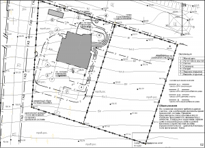
PD.MP, master plan of the site, first part of the Preliminary Design.
Before starting work, we’re familiarizing ourselves with the site and surroundings. The easiest way to do this is to go to the site, but photographs plus satellite data are just as good. This is necessary in order to determine the location of the house, its entrance, and its height. Topography of the site is desirable, and if the site is located in a populated area, or if it is outside the city but has uneven terrain, then you simply cannot do without topography of the site. Such a topographic survey should be on a scale of 1:500, display 1) the relief, 2) all above-ground buildings and structures, 3) underground utility networks, and 4) the boundaries of the site in full accordance with the current cadastral plan. It is advisable to transfer the topography to the architect in DWG (AutoCAD) file format.
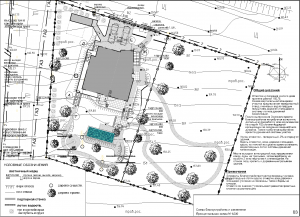
The master plan consists of three parts: MP-1, arrangement of buildings and structures with a vertical layout (their location vertically, relative to the ground and roads);MP-2, schematic diagram layout of utility networks within the site (water supply from the well to the buildings, sewerage from buildings to the septic tank, electricity, gas, heat); MP-3, a schematic diagram of the improvement of the site and its landscaping (scheme of paths and platforms, areas for planting trees for various purposes, water elements – ponds, streams, pools).

So, let’s begin – MP-1.
Location of buildings and structures with a vertical layout (their location vertically, relative to the ground and roads)
The first step in the work is to draw restriction lines on the site plan and geta spot of development possibilities. What restrictions are meant:
1. Distances from the boundaries of adjacent landholdings and from the street; 2. Sanitary and fire breaks from houses in adjacent sites.3. Distances from power lines, engineering structures, water bodies, if there are any nearby (sanitary gaps);4. If there are already materials from geological research of the soils of the site, then draw zones and lines of unfavorable geological factors (slip line on a landslide slope, peat/karst patch)
Now, knowing the area of development possibilities, we can make a concept for planting a building on the site. In most cases, the surroundings of the site do not limit the possibilities.
 Concept, the Principal Diagram of the Master Plan , PDMP – This is a diagram where we see the main buildings and structures, we understand the zoning of the site, where its different parts will have their own content. Most often, this scheme is developed in several versions.
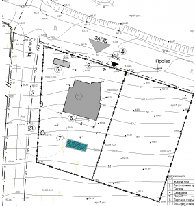
On the master plan of the site we place everything that is planned. In addition to the house itself, it can be a guest house or bathhouse, an outdoor pool or gazebo, a stream or pond, a garage, an open or covered parking lot, etc. These are already full-fledged solutions for the master plan of the site, the next level of specificity after the PDMP – but not yet final. The fact is that at the same time we decide how buildings and structures will “sit” in the topography of the site, i.e. vertically. It is best to do this by cutting across the entire area, which is what we are doing for this purpose.
 We decide what the first (ground) floor level will be relative to the level of the site, relative to the street level. Only later, when we receive the geologists’ report and add a geological section to the drawing, our decisions may change. As can be seen in this example, at a depth of 2 – 3 meters there were low-subsidence soils, and we changed the vertical planting in order to increase the distance from the foundations to this soil’s layer; we also had to change the concept of the building – we abandoned the basement.
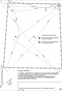 At this point in the process, it is advisable to pause and order geological research of the soils of the site. We give a diagram of the location of the building area on the site, we give points for drilling exploration wells (see image). And having already received the geological results, we continue our work. We continue without returning to the first stage, MP-1 – or change the location of the house if the geology underneath reveals complex soils and moving the house will allow the use of less expensive foundations.
I would like to note that complex soils are not found often, unless subsidence or landslide soils occur on hilly areas, peat or peaty soils on plains are even less common, but research still needs to be done.
Soil geology of your site – why it is needed, why it is important.
 OK, everything has been decided with the building site, and now it needs to be clarified – in terms of size, configuration, entry position. We are making PLS, the Principal Layout Scheme of the first floor. It is important to do this precisely at this stage – the placement of the building – because we need to get in the layout of the house not only household amenities, but also architectural qualities – views from windows, from terraces, convenience of entrances and exits from the house, and most importantly – we need to know although the dimensions of the house would be inaccurate. The planning scheme is fundamental; we operate with the areas of the rooms, placing them in a certain logic of our plan, creating either a floor with open spaces divided into zones, or a rigid system of rooms connected by corridors and halls. At this stage, it is also possible to adjust the Design Assignment if the diagram reveals previously unnoticed opportunities (or obvious absurdities of the Assignment).
Houses on a slope are most likely more interesting than others.
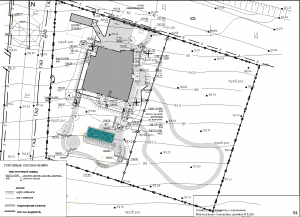 If the site is on a slope, characterized by relief, then the paths on it they will run along ledges, with stairs at drops, and here the designer’s task is to calculate the slopes of the paths (drainage), the number of steps, and the marks of the retaining walls that appear. Yes, at all differences in relief of more than half a meter there will be retaining walls made of reinforced concrete. At the stage of the WD, Workshop Drawings, the Master Plan section will be continued by design specialists, among whom will be a civil engineer, who will design all the retaining walls. But now, at the preliminary design stage, the architect must formulate his vision of these walls and give them a clear geometric definition – the shape in plan, the top marks. This example shows the walls that hold the ground along the flights of stairs.
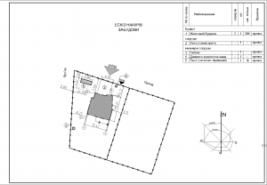 Sketch of Development Intentions is the same drawing of the master plan of MP-1, with the addition of formal attributes and marking sizes that eliminate all possible questions about the compliance of our solutions with regulatory requirements: from the house to the borders, to the septic tank and well, to trees and electric transmission lines, etc., etc.
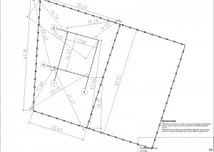 In order to make a truly useful Layout Drawing, we again need a topographic survey, where such objects on the ground are given, from which you can build your own coordinate system – the axes of the building. The corner points of the fence are ideal for us; if they exist in nature, power line supports will also work – everything that is solid and displayed on your topography can be a reference point for construction.
So, the section of the Master Plan of the Preliminary Design has been completed, all its three components, MP-1, -2, -3 have been completed, and as a result we have the following drawings:
MP-1.
Scheme of urban planning restrictions of the site;
Site development concept;
General plan of the site, its horizontal layout (all buildings and structures on the site);
Vertical layout (vertical position of all buildings and structures on the site, which means the level of their floor or top relative to ground level); for areas on a slope, a cut is also made along the slope;
Assignment to geologists (to conduct surveys on the site);
Layout Drawing (for the builders to lay out the axes of the building);
Sketch of Development Intentions (to be submitted to the local authority);
Schematic diagram of the first floor of the house;
MP-2
Schematic diagram of on-site utility networks;
MP-3
A schematic diagram of the improvement and landscaping of the site; for sites on a slope, the vertical planning of the improvement elements is also carried out (calculation of the height marks of the tops of the elements – paths, platforms, retaining walls).
This is what these drawings look like, using the example of the preliminary design of the Siverka project – drawings of the MP section of the Preliminary Design, PDF.
PD.AS, house architecture, second part of the Preliminary Design.
Since we already have the Principal Layout Scheme, PLS, ready, it remains to develop this concept into completely specific solutions for plans, and with them elevations, structures and engineering support. Let’s start PD.AS.
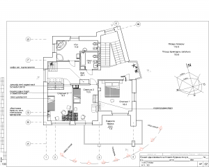 Continuing what was started at the master plan stage, the previously adopted concept diagram is being finalized, and at the same time the structures are being decided (how cover the spans with panels or a monolith; what structures to use, walls or columns; how the rafter beams will lie and what they will be made of; also with lintels over the openings) and ventilation (placement and size of ventilation shafts), sewerage (placement of risers and plumbing equipment). At the same time, the appearance of the future building does not vanish from view, because the next stage is elevations and sections.
 With the help of elevations and sections, as a rule, you can fully experience the shape of the “body” of the building for houses of traditional architecture, without angular or curved shapes. Having decided on the image of the building on the elevations, the architect can be completely sure that the building will be perceived in the same way in reality.
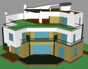
You can view this model in the free application Autodesk Free Online File Viewer (you can bring your laptop to the meeting, on which we will conduct the first viewing of the model together, in three steps – upload the file, open one of the ready-made views, turn it “in hands”).
Another option is possible, watching a video where we see the same model in rotation.
House’s structures at the sketching stage.
It is important to agree on fundamental decisions with the contractor now, when the project is at this level of development. Of course, it will be possible to order adjustments to the project after its completion, when all the calculations have been made and all the main and detailed decisions are ready, and when the hired contractor puts forward his requirements and wishes for construction solutions – but it is still more advisable to work out such issues on time, right now, at the stage of fundamental decisions.
Heat saving in a house, fundamental solutions.
Let’s summarize what we got at the end of the Preliminary Design stage, PD.AS – sample of AS section of Preliminary Design, PDF. First, let’s go through the minimum program, these are drawings with our solutions: Additional SAMPLE Preliminary Design (MP and AS drawings, download from the cloud) PD.AS is ready, what next? That’s all, after a short pause with the obtaining a Development Passport and coordination of decisions with the contractor, we move on to the second stage, WD – Workshop Drawings for construction. example of the process of developing a Preliminary Design
External walls and roofing are checked for heat saving efficiency. Using special calculations (view sample calculation) you can select the optimal thickness of the wall, its load-bearing part and insulation, as well as with the roof. Here it is important to select not only the thickness, but also the position of the layers in the structure in order to prevent the formation of steam (condensation) in the middle of the walls and its freezing. This is unacceptable; after several cycles of freezing and thawing, the structure begins to collapse, this process is called erosion or frost destruction. Therefore, the order of the layers of the structure is important – of course, if the structure is multilayer; if the wall consists of only one element that carries the load and retains heat (blocks of porous ceramics or autoclaved aerated concrete), then there is simply nowhere for steam to form.
What do we end up with after completing the PD.AS, and what next?
Floor planswith the names of the rooms, their areas, with the arrangement of sanitary appliances and technological equipment (hob or oven, kitchen sink and refrigerator, fireplace and heating boiler, central vacuum cleaner, etc.); the arrangement of everyday furniture here, as a rule, is not carried out, this is the prerogative of the ID section, Interior Design).
Floor plans with dimensions of rooms and openings.
Roof planwith technological equipment (external units of air conditioners / heat pump, solar collectors, etc.).
Plan of the underground/basement with technological equipment (heating equipment, sewerage, pool water treatment, etc.), with the dimensions of the rooms and openings.
House elevations indicating the type of finishing.
House elevationswith opening sizes.
Sections of the house with height dimensions.
Thermal engineering calculation of walls, attic floors (for houses with a pitched roof), combined coverings (for houses with a flat roof) – for compliance with standard requirements.
In the event that, as mentioned earlier, the building has a complex shape, or just at the request of our customer, an additional 3D computer model is carried out, PD.3D-1 (see above).
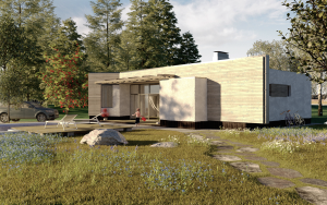
If extreme accuracy in details and display of the decoration of the house are relevant, then the 3D-model is visualized, with the addition of details, selection wall materials, imitation of landscape – this is PD.3D-2 (see above)
Now it is necessary to coordinate construction solutions with the contractor. We are preparing a Construction Solutions Approval Card (see above, with a sample in PDF), the project customer transfers it along with the Preliminary Design (in full, PD.MP and PD.AR) to the contractor, who gives his confirmation. Or it gives adjustments that we take into account at the next stage, the development of the WD, Workshop Drawings for construction. In addition to the understandable task of ensuring the adequacy of the project’s solutions, its full compliance with the conditions of the site and the capabilities of the contractor and the local construction market, this procedure prevents unscrupulous contractors from manipulating these factors in competition with their colleagues (here’s how in these situations).
Another important (and mandatory) action is to submit a Sketch of Development Intentions, SDI, to the local department of Urban Planning and Architecture, to receive a Site Development Passport there (what documents are required for this). There, a specialist architect of the department will develop a master plan for the site based on the ENZ submitted by you. The SDI already includes a general plan of the site – the way you and I see it, but this specialist has the right to adjust the position of the house on the site, which sometimes happens. Having received the Development Passport and discovered changes there, we make adjustments to our project, sometimes significant.
